Front-Mounted LCD with Custom Firmware for Ender 3 V2
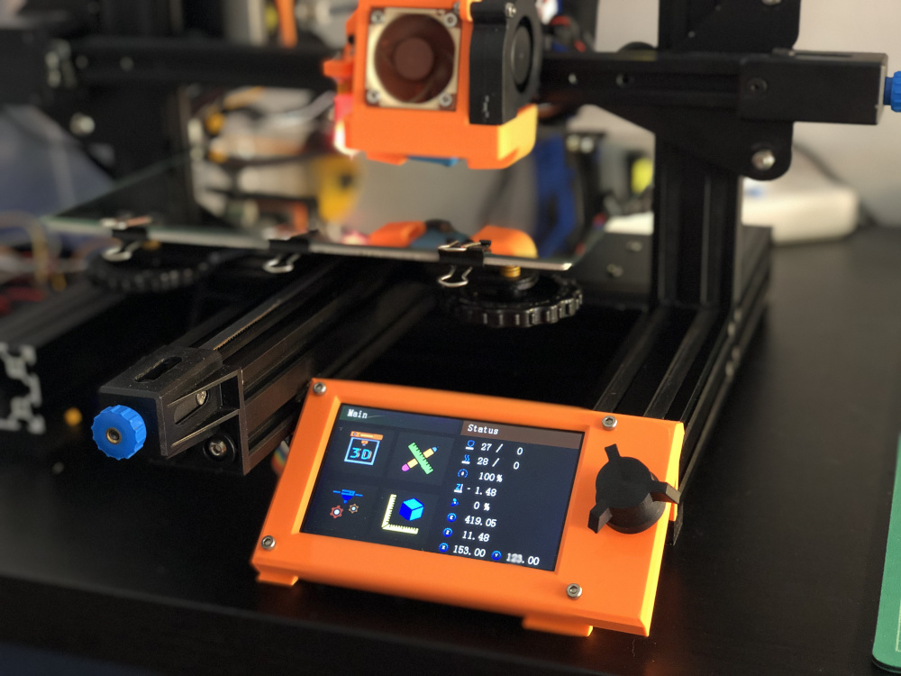
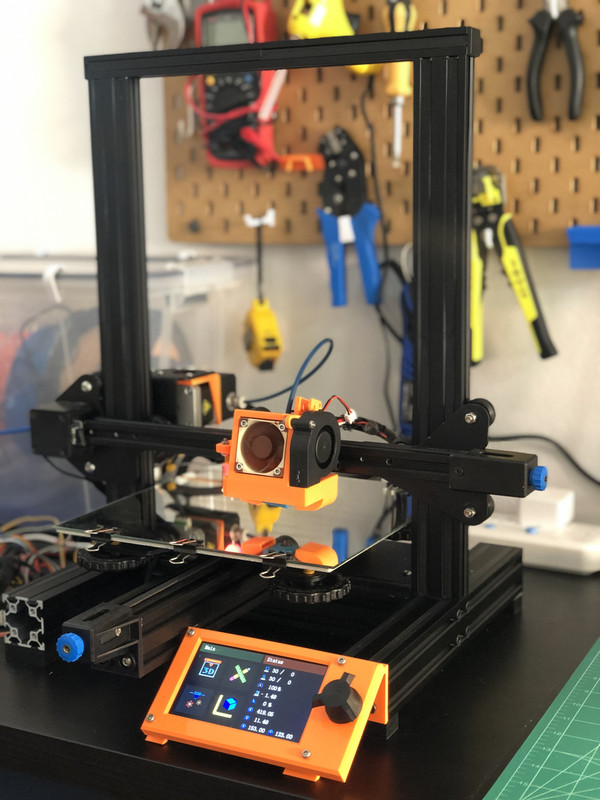
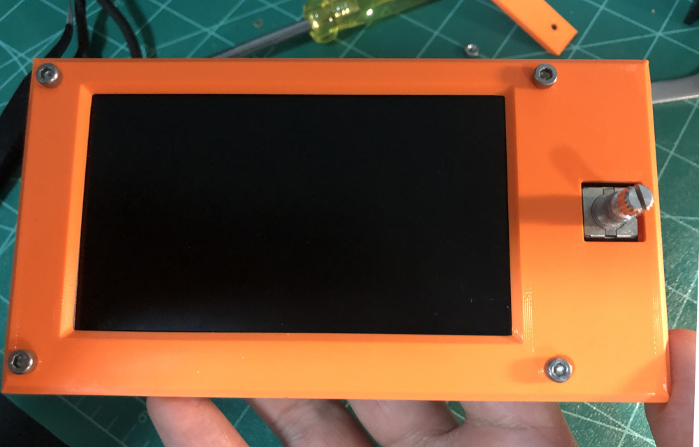
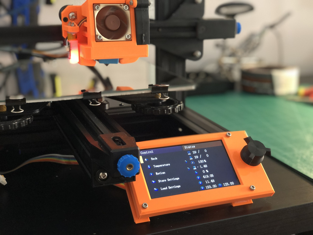
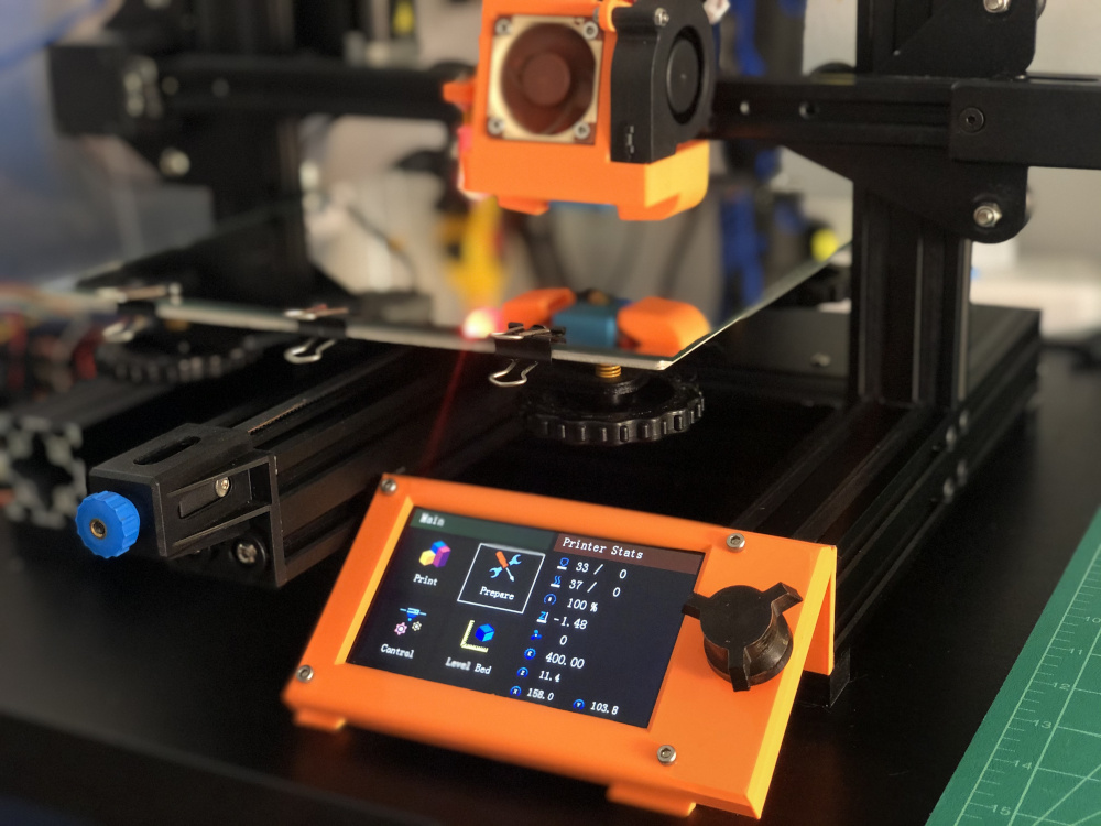
Creality ditched matrix LCD in favor of a fancy colorful all-blue LCD in Ender 3 V2. Except they forgot to develop a decent firmware for it and they mounted it in the worst spot they could possibly find. Heaven knows how many times I have hit this display accidentally. Is it possible to design a better LCD panel to decrease printer’s footprint and make it more compact? To find out, I wasted a few weekends to create this first otiose thing:
What you see is not an MK3S, it is the Ender 3 V2’s stock LCD with a new cover, mount and firmware. Here is what I’ve done:
- CAD the Panel (Completed) : I used the infamous open source FreeCAD to design the cover and the mount. This part was fun.
- Modify Marlin Firmware (Completed): This is the most challenging part. Why? Because Creality’s LCD code is just awful and has no support for landscape layout. So I have to modify the code substantially to make this work. This part is not fun at all. I love coding but Creality’s macabre DWIN code is just a nightmare.
- Modify Display’s UI Elements (Completed): The LCD (made by DWIN) has all the UI elements stored as low-res images in its local storage. These images had to be modified to fit in the new landscape layout.
There were several design principles I tried to adhere to:
- No Support: I don’t like supports. They waste filament and make the print ugly. So I made sure no support is needed for printing this panel.
- Print Time < 4 Hours: I did my best keep the print time under 4 hours. A lot of upgrades these days take all day and all night to print and waste a lot of filament.
- Minimalistic Design: No unnecessary features. Just a simple panel to conserve filament.
- Easy to Assemble: Well, I probably failed here. But let’s see. Hope the following instructions make it easier.
What You’ll Need
- lots of patience.
- M3 x 8mm or M4 x 8mm screw (1x): You can use the same screw and t-nut that is used to mount the stock display.
- T-nut (1x): Use the stock t-nut.
- M3 x 20mm screw (4x)
- M3 nut (4x)
- M5 screw (2x)
Note: This design assumes you are using the printer’s stock feet (~12mm tall). If you are using some customized damping feet that lifts your printer higher than the stock ones, the panel might end up hanging above the table surface.
Once you have everything, grab some munchies (gummy bear?) and read on.
How to Print
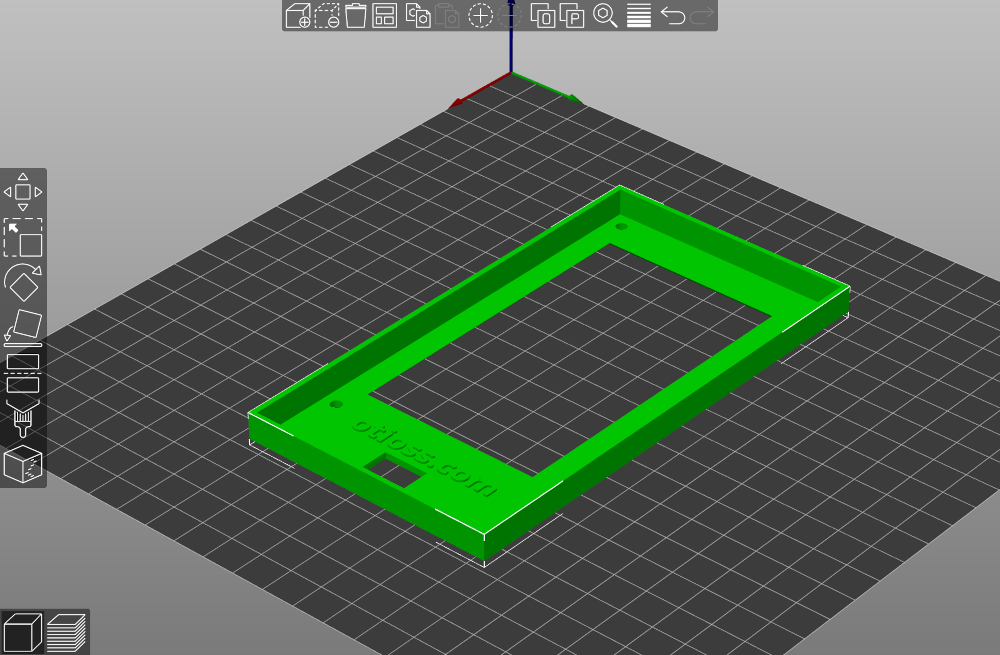
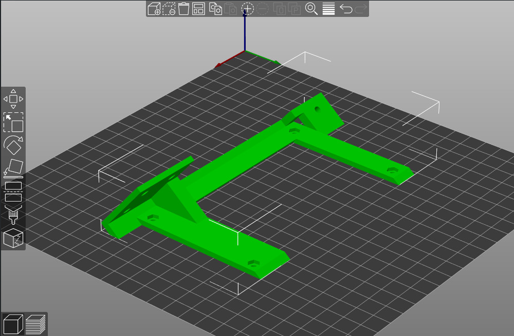
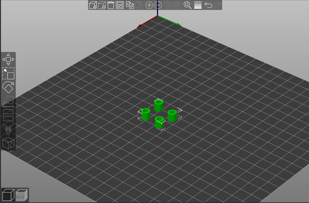
First, download all the files from thingiverse. Open slicer of your choice. Cura, Slic3r, Prusaslicer are all fine. I recommend to print in PETG or ABS with at least 40% infill. PLA could work as well but I am not sure if is strong enough for this project. Feel free to test PLA and let me know about result. I increased the print speed to 60mm/s without sacrificing quality much. Lay down the STL’s according to the pictures below and you won’t need any support.
lcd-cover.stl (print time ~ 1 hour 40 minutes):
lcd-mount.stl (print time ~ 2 hours 10 minutes):
spacer.stl (print time ~ 8 minutes for all four spacers):
knob (Optional)
You can use the stock knob, this one, this one or any other knob.
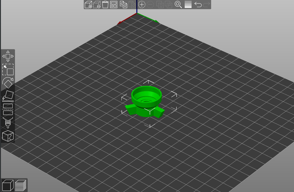
Assembly Instructions
-
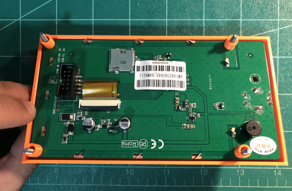
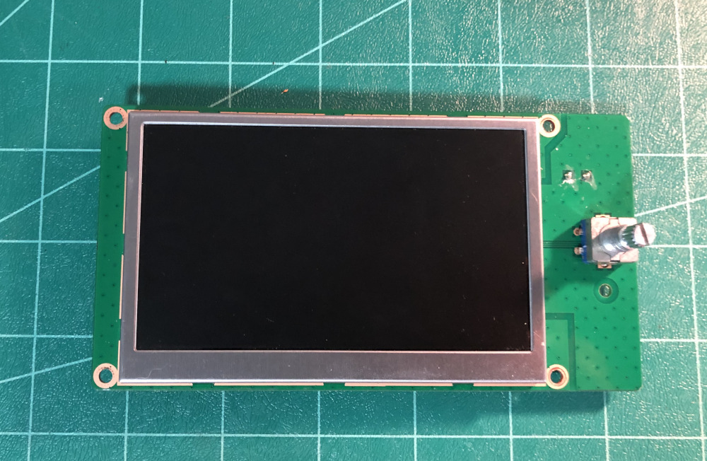
First, you need to tear down the stock LCD panel. Remove the the knob and all the screws. Here is a video to help you. The only thing we need is the PCB (set it aside for now):
-
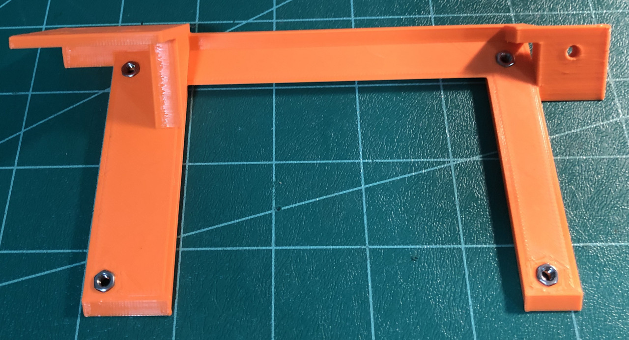
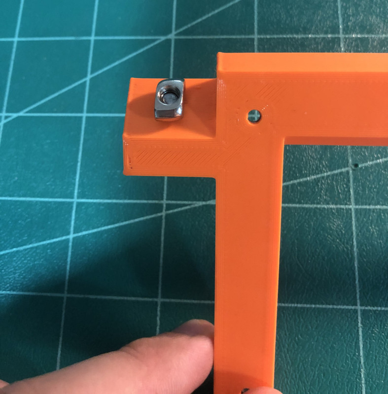
Take the lcd-mount and insert all four M3 nuts in the prepared slots according to picture below. I’ve designed them to be tight to make sure the nuts won’t fall later during assembly. You might have to press them firmly to make them go all the way in:
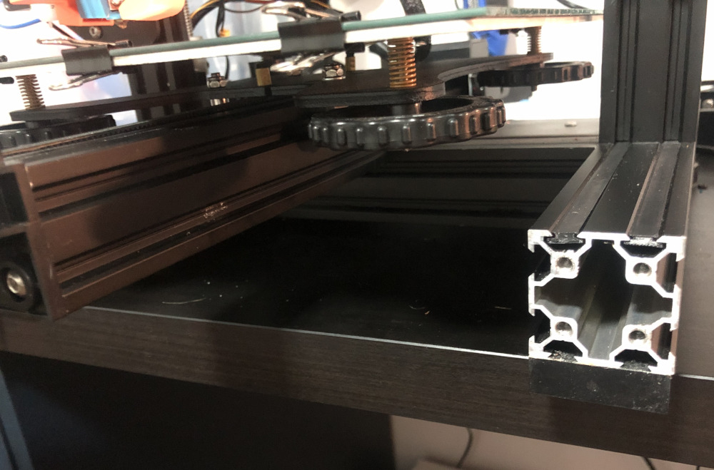
- Remove the plastic cap from the right aluminum extrusion. I highly recommend to remove the stock drawer (watch this video). If you decide to leave it as it is, you could try to remove the drawer’s knob and see if you can proceed with the assembly. Please let me know if this works.
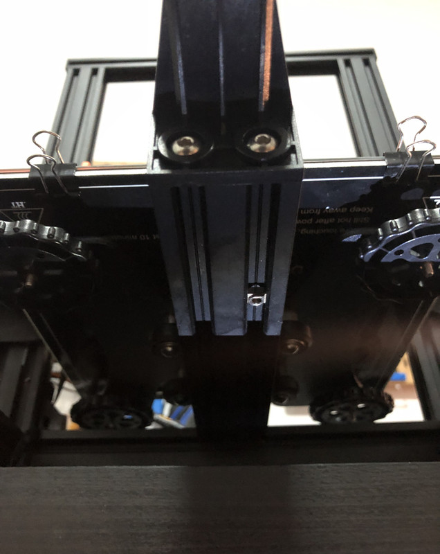
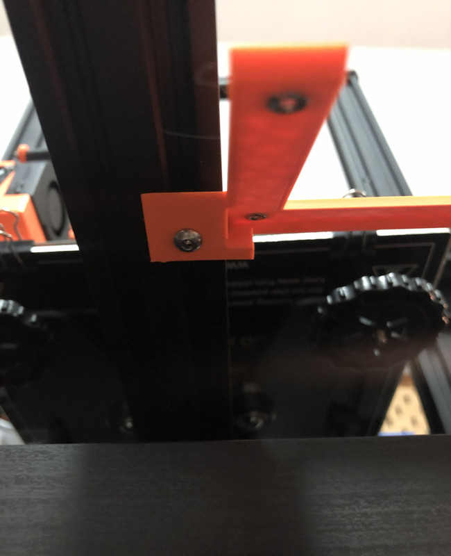
- Now we try to attach the left side of the mount to the printer. For this we use one T-nut and an M3 x 8mm screw. The left side of the mount gets attached to the bottom of the middle aluminum extrusion. You might have to lift up the printer a bit. I did a little trick by moving the printer to the edge of my table (be careful not to drop the printer) and work under it. I am not a big fan of T-nut screws. They are tricky and annoying. You have two options: (a) insert the T-nut at the bottom of printer and then screw:
or (b) insert the T-nut and screw in the mount and then attach it to the printer:
This is kind of important: Make sure the left side of the mount is aligned with the front of the right aluminum extrusion (where the right side of the mount will be attached to later on). Then tighten the screw under the printer:
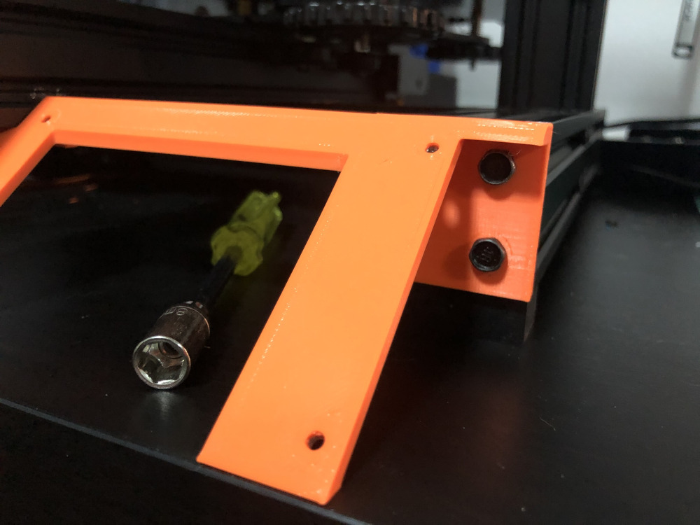
Ok, the left side of the mount is finished. Now for the right side, use two M5 screws. Actually I designed three holes for three M5 screws but that is a bit of overkill. Two is perfectly adequate.
Very well, you’ve just installed the mount successfully. Now let’s attach the lcd-cover to the lcd-mount. Pick up the PCB, put the cover on top of it and insert all four M3 x 20mm screws:
Insert all four spacers:
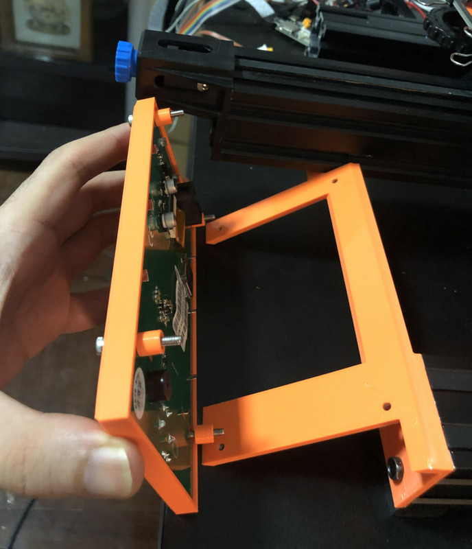
Carefully, install the cover+pcb in a slow tilt motion according to picture below. Move it slowly to prevent spacers from falling. First connect the bottom two screws and then slowly tilt the screen (maybe hold the upper two spacers with your hand to make sure they don’t fall) and attach the top two screws:
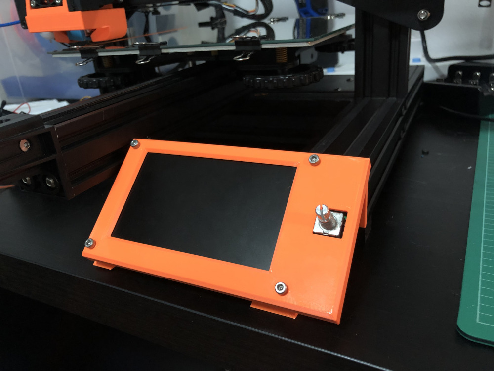
Once you are sure all screws and spacers are placed properly, tighten all four screws. please DO NOT over-tighten the screws as it might bend the cover. Just screw it tight enough so that the cover and LCD are attached to the mount firmly:
Now insert the knob (just press it). Plug the LCD cable and turn on the printer:
Congratulations! You successfully finished the installation.
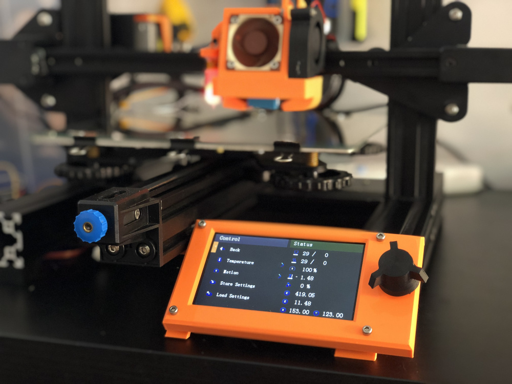
Now it is time to install the firmware.
Firmware
Ender 3 V2 uses the open source Marlin firmware. The LCD is controlled by DWIN LCD code (originally written by Creality) within Marlin firmware. There is no support for landscape layout in DWIN code so I decided to implement this feature myself alongside some other improvements:
I have compiled two variants of the firmware which you can download below. However I recommend you to configure and compile the firmware yourself instead of using these binary files:
- otioss-firmware-bltouch.bin: For BLTouch users (tested on my machine). Don’t forget to adjust your e-step and other settings after flashing firmware.
- otioss-firmware-non-bltouch.bin: For Non-BLTouch users (Not tested. Use with Caution. Please report your findings)
In what follows, I will show you how to configure and compile this customized firmware for your Ender 3 V2 3D printer. If you are a beginner with no experience regarding configuring and compiling Marlin, do not worry. With a bit of patience and experimentation, you can compile and install this firmware.
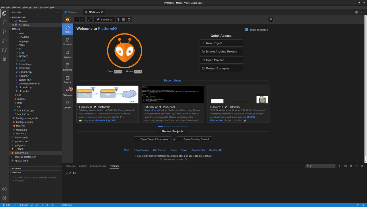
Install Git + Visual Studio Code + Platform IO. First make sure Git is installed on your system. Then install Visual Studio Code and then install PlatformIO within Visual Studio Code.
Download the Firmware. The firmware’s code is available on my github. Get a copy by issuing git clone command:
git clone https://github.com/otioss/Marlin.git
Opening Marlin: In Visual Studio Code go to file > open folder and select the Marlin folder you just downloaded cloned. After that, click on 2.0.x branch icon at the bottom left of the screen:
and from drop-down menu select origin/bugfix-2.0.x:
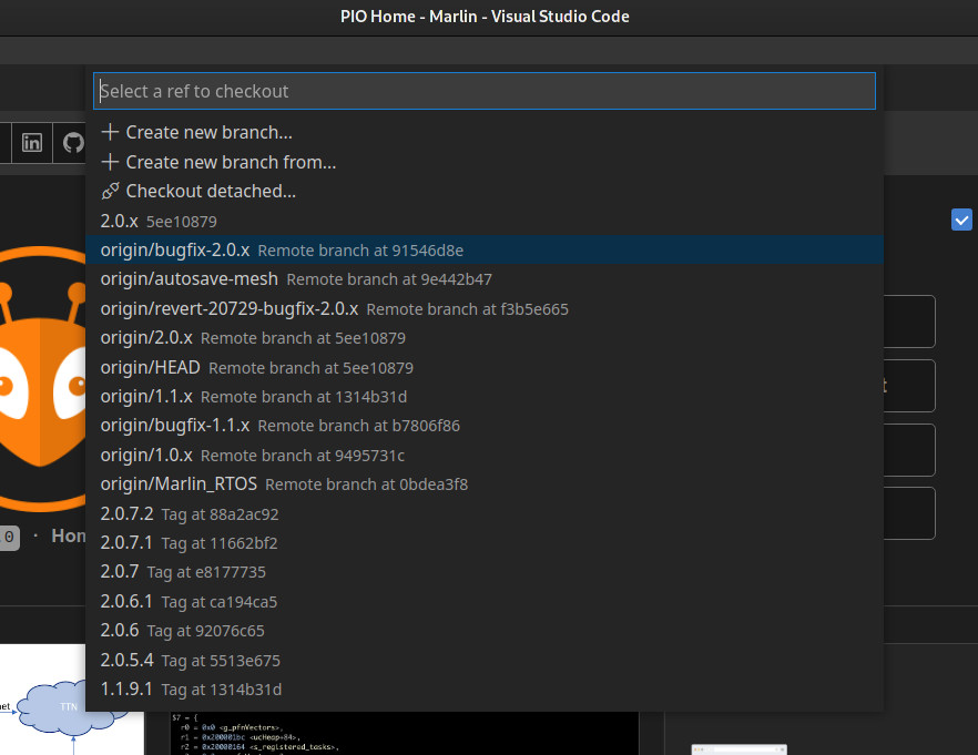
Now you can see the branch icon at the bottom left of the screen has changed to bugfix-2.0.x:
Configuring Marlin: This is the most important step. There are two main configuration files within Marlin firmware:
Marlin\Configuration.hMarlin\Configuration_adv.h
There are no fixed settings. Each printer is different and depending on your modifications/upgrades (ABL, custom extruder, all-metal hotend, etc) you need to adjust the settings according to your machine and preference. Marlin website has a definitive guide about these two files that I highly recommend. Generally, the configuration falls in one of the following categories:
-
BLTouch Users: If you have BLTouch installed on your Ender 3 V2, you can use the default configuration that comes with my Marlin repo you downloaded above. There might be some differences between my setup and yours. For example my e-step is 400 (for BMG extruder) so make sure you change it if you use stock or a different extruder (look for DEFAULT_AXIS_STEPS_PER_UNIT line). Actually you can change many of these settings with G-code commands later.
-
Non-BLTouch Users: Marlin developers provide configuration files suitable for stock Ender 3 V2. This is the best course of action for beginners. You can pretty much copy the content the Configuartion.h and Configuration_adv.h and replace them with the ones in Visual Studio Code. Read the settings again to make sure they match your printer.
Platform.ini: In Visual Studio Code, navigate to platform_ini, locate and set
default_envs = STM32F103RET6_creality
Board Model: Navigate to Marlin/Configuration.h and find #define MOTHERBOARD line. If you use the default V4.2.2 board that comes with majority of Ender 3 V2s, just set
#define MOTHERBOARD BOARD_CREALITY_V4
If you use the newer V4.2.7 board, set it to
#define MOTHERBOARD BOARD_CREALITY_V427
Enable Landscape Mode: This is enabled by default in my firmware so you do not need to change it. To double check, head to Marlin/src/lcd/dwin/dwin_lcd.h and make sure LCD_ROT is set to 1:
#define LCD_ROT 1
If in the future you want to revert to vertical portrait orientation, you can set it to 0. Also make sure both #define USE_STRING_HEADINGS and #define USE_STRING_TITLES are uncommented in Marlin/src/lcd/dwin/e3v2/dwin.cpp.
Tip: For those who wish to mount the panel on the left side of the printer, I have added the LCD_FLIP option. By default it is 0 which means the display knob ends up on the right side. If you set it to 1 the screen is flipped upside down with knob on the left side. In the future, I plan to provide a mirrored version, suitable for mounting the display on the left side of the printer.
Compilation: Click the little check mark ✓ button at the bottom of Visual Studio Code:
The compilation starts hopefully you see a success message:
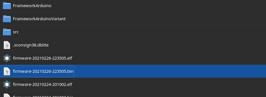
Locate the Firmware File. The final compiled firmware is stored in a file with .bin extension. If you look at terminal window (screenshot above) , you can find the location of .bin file which is usually something like this: .pio/build/STM32F103RET6_creality/firmware-{current date-time}.bin. Using your file browser, navigate to that directory and copy the .bin file to a Micro SD Card.
Flash Firmware Copy the .bin file to your Micro SD card. Make sure it is the only .bin file there with a new name (Visual Studio always produce files with unique names based on date/time). Insert the Micro SD card in your Ender 3 V2 printer and turn it on. You see black screen for a few seconds and then your printer boots with new firmware.
Congratulations! Hope everything goes smoothly for you. I recommend that you re-check your e-steps (e-step is shown in status area of the screen) and other settings before you start to print. If you have BLTouch, I recommend to run Level Bed and then Store Settings to create and save a new mesh of your bed. If you have any questions, don’t hesitate to contact me.
Skinning the UI (Optional)
Now it’s time to flash a new set of icons to the LCD’s memory. The DWIN LCD has a Micro SD card slot at the back that can be used to flash icons and other media to the LCD’s internal storage. The flashing procedure is a bit specific so please follow the instructions exactly as follows.
Format your Micro SD Card. The important thing is that your Micro SD card has to be formated in FAT32 with allocation size of 4096 (4K) bytes. It is very important the allocation size is 4K bytes. If not, the flashing won’t work. Make sure the Micro SD card is empty and there are no files there. I recommend not to use a Micro SD Card with an astronomical capacity (e.g. 256GB). An 8GB or 16GB Micro SD Card is perfectly fine.
Get the ICONS: The icons and boot logo are available on my github. Download the DWIN_SET folder.
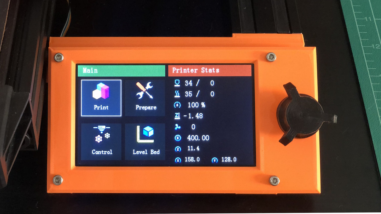
Flash Firmware: Copy the DWIN_SET to your Micro SD Card. Insert the Micro SD card in the back of your LCD’s Micro SD card slot and turn on the printer. You’ll see a blue screen for a few seconds followed by an orange screen. When you see the orange screen it means the flashing is complete. Turn off the printer, take out the Micro SD card and then turn the printer back on. If everything was done correctly, you should see the new icons:
Please note that this is still a work in progress. I plan to add many more features to this firmware in the future. If you like my work, please consider supporting my work on Pateron.
The comment section of this website is not fully-developed yet. Please leave your comments on thingiverse or contact me on Twitter.
